Part distortion is a frequent challenge in precision machining. This problem is particularly critical for thin-walled parts. The deformation of these thin-walled parts stems from a mix of thermal stress, mechanical forces, and internal material stress.
Key Insight: Successful machining of thin-walled components requires a clear understanding of these root causes. This knowledge helps prevent costly defects in all thin-walled parts machining operations.
Key Takeaways
- Heat from grinding causes thermal stress. This stress makes thin-walled parts expand and contract unevenly. This leads to permanent warping.
- Grinding forces can bend thin-walled parts. These parts are not stiff. This bending causes poor accuracy and bad surface finishes.
- Clamping parts too tightly causes distortion. The part bends while clamped. It then springs back to a distorted shape after release.
- Raw materials can have hidden stress. Grinding releases this stress. This makes the part change shape and warp.
Thermal Stress: The Primary Cause of Distortion
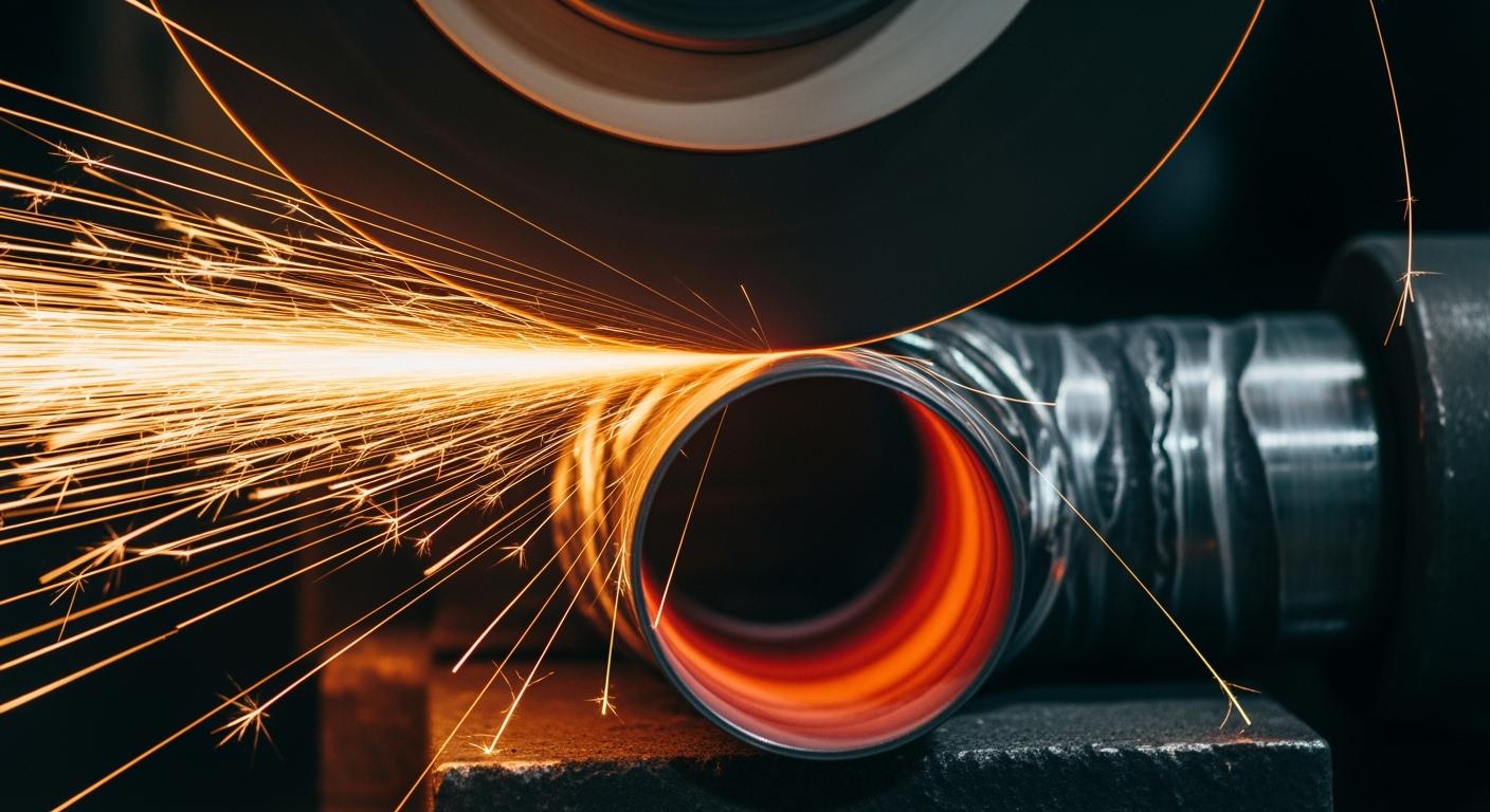
Heat is the primary adversary in the precision grinding of thin-walled parts. Nearly all the mechanical energy used in grinding converts into thermal energy. This intense heat, if not managed, causes expansion and contraction that leads to part distortion. Understanding how this heat is generated and what factors amplify it is the first step toward a solution.
How Grinding Heat Induces Warping
Grinding generates extreme heat in a very small contact zone. This thermal energy arises from a combination of physical actions. The process converts mechanical energy into heat through three main mechanisms:
- Friction: The rubbing action between the abrasive grains and the workpiece.
- Plowing: The displacement of material without forming a chip.
- Shearing: The actual cutting action that removes material.
This localized heat causes the surface layer of a thin-walled part to expand rapidly. However, the cooler bulk material underneath resists this expansion, creating compressive stress. As the area cools, the surface contracts, but this uneven cooling process results in tensile residual stress. If this stress is high enough, it causes permanent deformation of the thin-walled component.
Key Factors That Increase Thermal Stress
Several common machining mistakes can significantly increase thermal stress on thin-walled parts. Minimizing heat generation requires controlling these key variables.
Pro Tip: Pay close attention to your grinding parameters. Small adjustments can make a significant difference in managing heat and preventing defects in thin-walled parts.
An aggressive depth of cut is a primary offender. Deeper cuts increase grinding forces and enlarge the contact area between the wheel and the workpiece. This action generates more friction and makes it harder for heat to dissipate, raising the surface temperature.
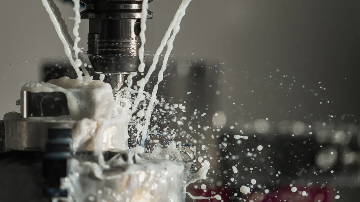
Insufficient coolant also leads to overheating. Without proper fluid application, workpiece temperatures can rise above the coolant’s boiling point. This creates a vapor film that insulates the surface, preventing the coolant from doing its job and causing thermal damage to the thin-walled part.
Finally, a dull or loaded grinding wheel contributes heavily to heat. A dull wheel rubs and plows the material instead of shearing it cleanly. This inefficient action generates far more friction and heat, compromising the integrity of heat-sensitive thin-walled parts.
Mechanical Stress and Grinding Forces
While thermal stress is a major culprit, the physical force of the grinding wheel is an equally significant cause of distortion. Thin-walled parts have low structural rigidity. They cannot withstand the mechanical pressure exerted during machining. This force can bend or deflect the non-rigid walls, leading to immediate or permanent deformation. Effective vibration control methods are essential for stability in the cutting process.
Physical Deflection of Thin-Walled Parts
The grinding wheel applies force directly to the workpiece surface. This force has two components: a normal force pushing into the part and a tangential force acting along the cutting path. For robust parts, this is not an issue. However, for thin-walled parts, these forces cause the wall to bend away from the wheel. This deflection leads to dimensional inaccuracies and poor surface finishes.
Grinding parameters directly influence these forces. A higher feed speed increases the material removal rate, which elevates the cutting force. Similarly, a deeper cut requires more force, increasing the risk of part deflection. This instability often results in vibration and chatter, which are detrimental to precision machining. Managing these forces is a primary goal in machining thin-walled parts. The process requires careful planning to maintain stability.
Challenges in Machining Thin-Walled Parts
The main difficulty in machining thin-walled parts is their lack of stability. The low rigidity causes the workpiece to deform under cutting pressure, leading to inconsistent material removal. This creates a cycle of vibration and chatter that compromises the entire machining operation. The challenges machining thin-walled parts are significant. Addressing vibration and chatter is key. Effective vibration control methods are needed to ensure a smooth cutting process.
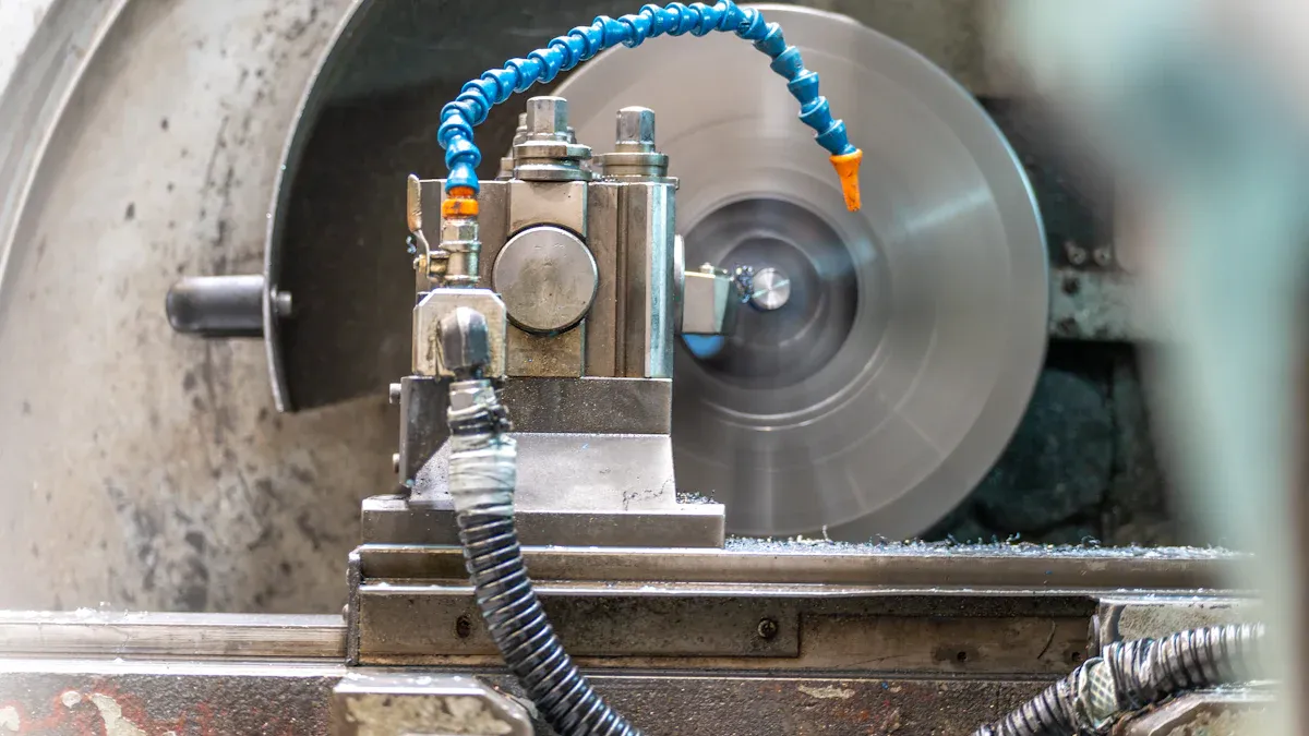
Solution Spotlight: Reducing the grinding force is the most direct way to improve stability. A sharp, efficient grinding wheel requires less pressure to perform its cutting action. This minimizes the physical push on the workpiece.
Using a correctly specified wheel, like Aimgrind’s diamond grinding wheels, is a critical step. These advanced wheels are engineered for superior cutting efficiency. Their sharp, durable abrasive particles micro-fracture to self-sharpen, ensuring they require minimal force to remove material. This reduces mechanical pressure, minimizes vibration, and is one of the most effective vibration control methods for machining thin-walled parts. A sharp wheel not only prevents mechanical distortion but also generates less heat, addressing both primary causes of failure in machining thin-walled parts.
Fixturing Forces and Clamping Errors
The way a workpiece is held is just as critical as the grinding process itself. Improper clamping is a direct cause of distortion in thin-walled parts. The very forces meant to provide stability can introduce stress that ruins dimensional accuracy. Effective cnc workholding is essential for successful machining.
How Improper Clamping Deforms Parts
Excessive clamping pressure physically bends a part before the grinding wheel makes contact. This is a common issue with thin-walled parts due to their low rigidity. The part is held in an elastically deformed state during the machining operation. After grinding is complete and the clamping force is released, the material “springs back.” This elastic recovery causes the part to settle into a new, distorted shape, often resulting in elliptical or polygonal forms instead of true circles.
This spring-back effect means a part that was perfectly in-spec while clamped will fail inspection once released. The goal of any cnc workholding setup is to secure the part without altering its natural state.
Improper clamping can lead to several defects:
- Surface Dents: High clamping force can leave impressions on the part’s surface.
- Internal Stress: Uneven clamping introduces stress that causes warping after release.
- Delamination: Poor support can cause vibration, leading to layer separation in composite materials.
Achieving stability without deformation requires a balanced approach to clamping.
Common Fixturing Mistakes to Avoid
Many fixturing errors are preventable. A primary mistake is applying too much force in the wrong places. This compromises the stability of thin-walled parts. Another common error is using worn or poorly maintained fixtures. Loose components in a fixture introduce play and vibration, making precision impossible.
Choosing the right cnc workholding method is the best way to avoid these issues. The ideal fixture distributes clamping pressure evenly to provide stability without causing stress. For thin-walled parts, specialized cnc workholding solutions are often necessary.
| Workholding Method | How It Works | Best For Thin-Walled Parts |
|---|---|---|
| Adhesive Workholding | Bonds the part to a fixture with wax or glue. | Ultra-thin or irregularly shaped parts. |
| Magnetic Workholding | Uses magnets for even force on ferrous materials. | Flat steel or iron components. |
| Expanding Mandrels | Grips the part’s interior diameter. | Hollow cylindrical or tubular parts. |
| Vacuum Workholding | Uses suction for uniform pressure distribution. | Plate-style parts and complex geometries. |
Selecting the correct cnc workholding strategy is fundamental to successful machining. It ensures the part remains stable and true throughout the entire process, preventing costly clamping-induced failures.
Internal Residual Stress Release
Sometimes, a part is destined for distortion before the grinding wheel ever touches it. This is due to internal residual stress. This hidden stress is locked within the material from its initial manufacturing processes. The subsequent machining operation does not create this stress; it simply releases it.
How Pre-Existing Stress Causes Warping
Raw materials often contain significant internal stress. Processes like casting, forging, and heat treatment introduce these stresses. For example, quenching steel parts creates high residual stress. Even additive manufacturing introduces stress as material is built layer by layer. The material is in a state of balanced tension and compression.
Grinding removes material from the surface of thin-walled parts. This removal disrupts the internal stress balance. The remaining material redistributes the stress to find a new equilibrium. This redistribution forces the part to change shape, causing warping. The primary cause of this distortion is the uneven release of these pre-existing tensions. This is a common challenge in the machining of thin-walled parts.
Identifying High-Risk Thin-Walled Components
Certain materials and geometries are more susceptible to problems from residual stress. Identifying these high-risk thin-walled parts early allows for better process planning. The machining strategy must account for these factors.
Note: Some advanced techniques, like the Layer Removal method, can measure bulk residual stress in raw material blanks before machining begins. This provides valuable data for process optimization.
High-risk materials often include:
- High-strength aluminum alloys
- Titanium alloys like Ti-6Al-4V
- Hardened and heat-treated steels
- Nickel superalloys
Part geometry also plays a critical role. Thin-walled components with the following features are at a higher risk:
- Asymmetric features that lead to uneven material removal.
- Large aspect ratios (long and slender shapes).
- Curved walls, which can hold slightly more stress than flat walls.
Careful consideration of these factors is essential for successfully producing precise thin-walled parts.
Distortion in thin-walled parts stems from thermal stress, mechanical force, improper clamping, and residual stress release. A systematic approach to the machining process is essential for achieving accuracy. This includes optimizing clamping for better accuracy and selecting the right tools. Proper clamping ensures the accuracy of thin-walled parts. For precision machining of thin-walled parts, choosing a superior abrasive like those from Aimgrind is a critical step toward achieving the highest accuracy and eliminating distortion from your clamping and machining operations.
FAQ
What is the main cause of distortion in thin-walled parts?
Heat is the primary cause. Grinding generates intense thermal stress, causing the part’s surface to expand and contract unevenly. This movement leads to permanent warping and dimensional inaccuracies. Proper heat management is essential for precision.
How does a grinding wheel prevent mechanical distortion?
A sharp, high-quality wheel requires less physical pressure to cut material. Reduced grinding force minimizes the bending or deflection of non-rigid thin walls. This helps maintain the part’s original shape during the process.
Is tighter clamping better for securing thin parts?
No. Excessive clamping force can bend the part before grinding begins. The part then springs back to a distorted shape after release. Proper workholding secures the part without introducing new stress.
Why does a part warp even with a perfect grinding setup?
The raw material may contain hidden internal stress from prior manufacturing. Grinding removes material and releases this balanced stress. The part then changes shape to find a new equilibrium, causing it to warp.