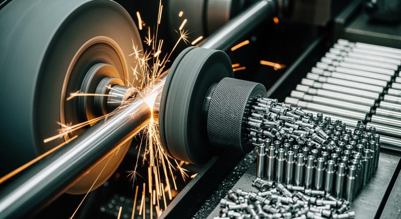
Mastering the centerless grinding process comes down to controlling three fundamental areas. Success in this demanding grinding process requires a systematic approach. This guide will help you achieve consistent dimensional accuracy and a superior surface finish. Your focus should be on the core pillars of the centerless operation to improve accuracy.
The three pillars of control are:
- Precise geometric setup of the machine.
- Optimized process parameters.
- Diligent maintenance of key components.
Key Takeaways
- Good centerless grinding needs three things: correct machine setup, best settings, and careful upkeep.
- Set up the machine geometry correctly. This means adjusting the workblade height and angle, and aligning the guides. This prevents mistakes like parts that are not round or straight.
- Adjust the machine settings. Control the regulating wheel speed and grinding wheel speed. This helps you remove material well and get a smooth finish.
- Keep your machine parts in good shape. Dress the grinding wheel often. Check and replace the workblade when it wears out. This keeps your parts consistent and high quality.
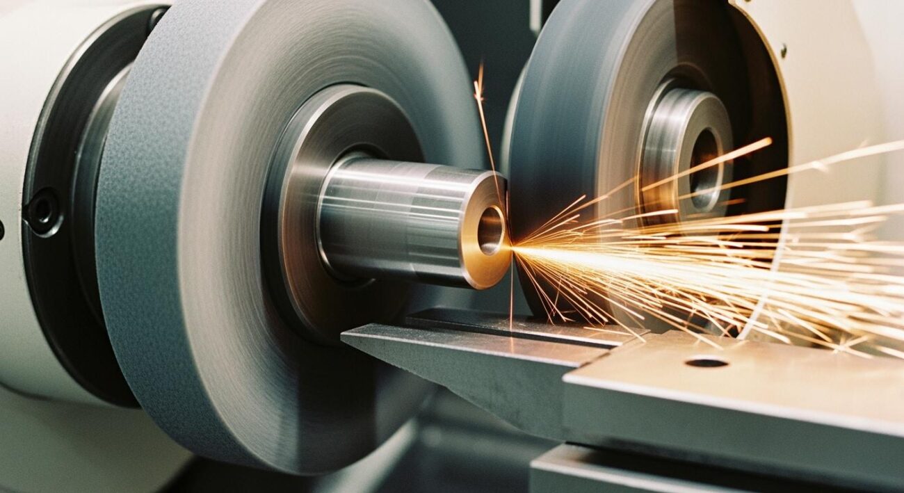
Mastering Setup Geometry
A precise geometric setup is the foundation of any successful centerless grinding operation. Incorrect alignment is a primary source of dimensional errors. Getting the geometry right from the start prevents issues like taper, chatter, and out-of-roundness, ensuring a stable grinding process.
Workblade Height and Angle
The position of the workblade directly influences the rounding action on the workpiece. For most applications, perfect roundness is achieved by positioning the workpiece above the centerline of the grinding and regulating wheels. Raising the workblade height—for instance, to 0.375 inches above the wheel centerline—helps the workpiece achieve roundness faster. However, raising it too high can cause the workpiece to lift off the blade.
The angle of the workblade is equally critical.
Pro Tip: A top blade angle of 30 degrees, sloping down toward the regulating wheel, is an excellent starting point for most jobs. This angle helps keep the workpiece in firm contact with the regulating wheel. It prevents the workpiece from spinning up to the speed of the grinding wheel, which ensures controlled material removal. A steeper angle can accelerate the rounding action.
Some applications, like bar grinding, may require setting the workblade below the centerline. This setup can help reduce vibration on a long workpiece.
Inlet and Outlet Guide Alignment
Proper guide alignment ensures the workpiece travels smoothly through the centerless machine. The inlet guides position the workpiece as it enters the grinding zone, while the outlet guides support it upon exit. These guides must be perfectly parallel to the direction of travel.
Any misalignment can cause the workpiece to twist or shift. This movement introduces errors as the workpiece contacts the grinding wheel. Misaligned guides are a common cause of tapered or barrel-shaped parts. A correctly aligned workpiece will enter and exit the grinding process without any deviation, leading to consistent diameter and straightness from end to end. This step is vital for holding tight tolerances on every workpiece.
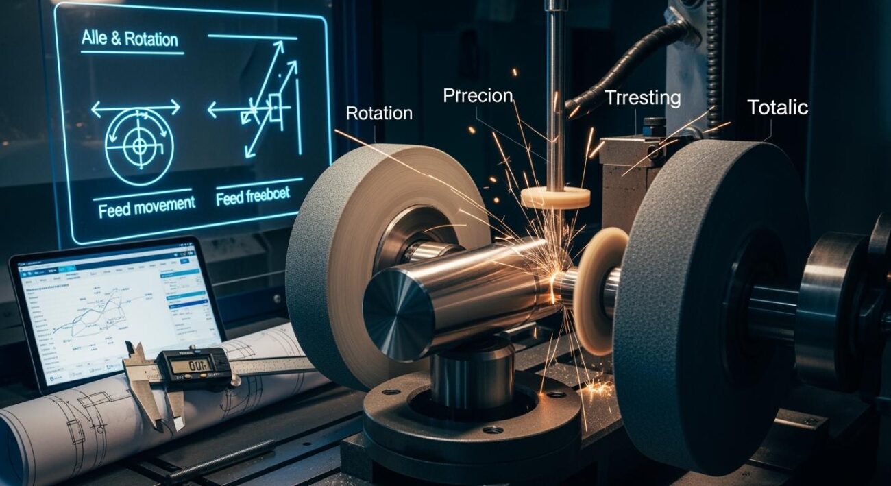
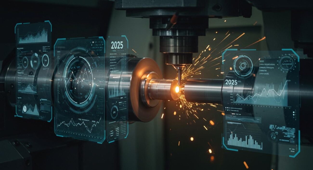
Optimizing Centerless Grinding Parameters
Once your machine geometry is correct, your next focus is on process parameters. These settings are the “dials” you turn to control the grinding action. Fine-tuning them is essential for balancing productivity with precision. The right parameters transform a good setup into a high-performance grinding process.
Regulating Wheel Control
The regulating wheel is the control center of the centerless operation. It serves two critical functions. First, it dictates the rotational speed of the workpiece. Second, it controls the axial feed rate in through-feed grinding.
Slowing the regulating wheel speed increases the number of times the grinding wheel contacts the workpiece per revolution. This action produces a finer surface finish. A faster regulating wheel speed removes material more quickly but results in a rougher finish. For extremely fine finishes, such as those under 5 RMS, a very slow regulating wheel speed is necessary.
Through-Feed Rate Control
In through-feed centerless grinding, the regulating wheel is tilted at a slight angle, usually between +1 and +3 degrees. This tilt creates the axial force that pushes the workpiece through the machine. A larger angle increases the feed rate and productivity. A smaller angle slows the workpiece down. Finding the optimal angle is key. An angle that is too small can cause the workpiece to stall, while an angle that is too large can cause taper or spiral marks on the workpiece.
The speed and angle of the regulating wheel must work together. They directly influence the quality and efficiency of the entire grinding process.
Grinding Wheel Speed and Feed
The grinding wheel speed and feed rate determine your material removal rate (Q’w). This rate measures how much material is removed from the workpiece over time. You must adjust this rate for roughing and finishing passes.
- Roughing Passes: The goal is to remove material quickly. This requires a higher feed rate.
- Finishing Passes: The goal is to achieve final size and a superior surface finish. This requires a slower feed rate and a lighter depth of cut.
For many materials like stainless steel, a grinding wheel speed between 5,000 and 6,000 surface feet per minute (SFPM) is a good starting point. The specific Q’w can be calculated for different centerless methods.
Calculating Material Removal Rate (Q’w):
- Traverse Grinding:
Q'w = (ae * nw * dw * π) / 60ae= depth of cutnw= grinding wheel rpmdw= workpiece diameter
- Plunge Grinding:
Q'w = (vf * dw * π) / 60vf= infeed speeddw= workpiece diameter
Understanding these formulas helps you quantify your process. You can make precise adjustments to meet cycle time and quality targets. Each workpiece requires a balanced approach to speed and feed. This balance ensures the workpiece meets specifications without introducing stress or defects. Proper control over these parameters is fundamental to successful centerless grinding.
Maintaining Component Condition
A perfect setup and optimized parameters will fail if your machine’s components are worn. The condition of your grinding wheel and workblade directly impacts the final quality of every workpiece. Diligent maintenance is not optional; it is essential for a stable and predictable grinding process.
Wheel Dressing and Truing
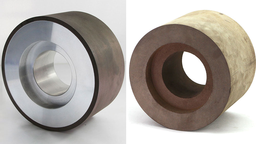
Proper dressing is the key to consistent size control. This process ensures the grinding wheel face is true, sharp, and free of debris. The speed of your dressing diamond directly impacts the wheel’s surface and the finish of the workpiece. A faster traverse speed creates a smoother wheel surface, which improves the workpiece finish. A slower speed results in a coarser, sharper wheel for aggressive material removal. However, improper speed can cause an out-of-round condition called “lobeing” on the wheel, which transfers imperfections directly to the workpiece.
When grinding hard materials like ceramics or composites, wheel stability is even more critical. High-performance wheels, such as Aimgrind‘s diamond grinding wheels, are designed for this challenge. Their robust construction ensures they hold their form precisely after dressing. This leads to consistent part quality and extends the time between dressing cycles, improving the efficiency of the entire centerless grinding operation. A stable wheel guarantees that every workpiece is ground to the same exacting standard.
Workblade Inspection and Replacement
The workblade provides critical support for the workpiece during the grinding process. A worn or damaged blade will compromise both dimensional accuracy and surface finish. Regular inspection is mandatory for preventing defects.
Pro Tip: A worn workblade is a primary cause of poor part quality. Look for these common signs that indicate it is time for a replacement:
- Scoring or visible groove wear on the blade surface.
- A rough or chipped blade, which can transfer imperfections onto the surface of the workpiece.
- Uneven wear on the blade, which prevents the workpiece from rotating uniformly and causes roundness errors.
Ignoring these signs will introduce inconsistencies that are difficult to diagnose elsewhere. Replacing a worn workblade is a simple, cost-effective measure to protect the quality of each workpiece.
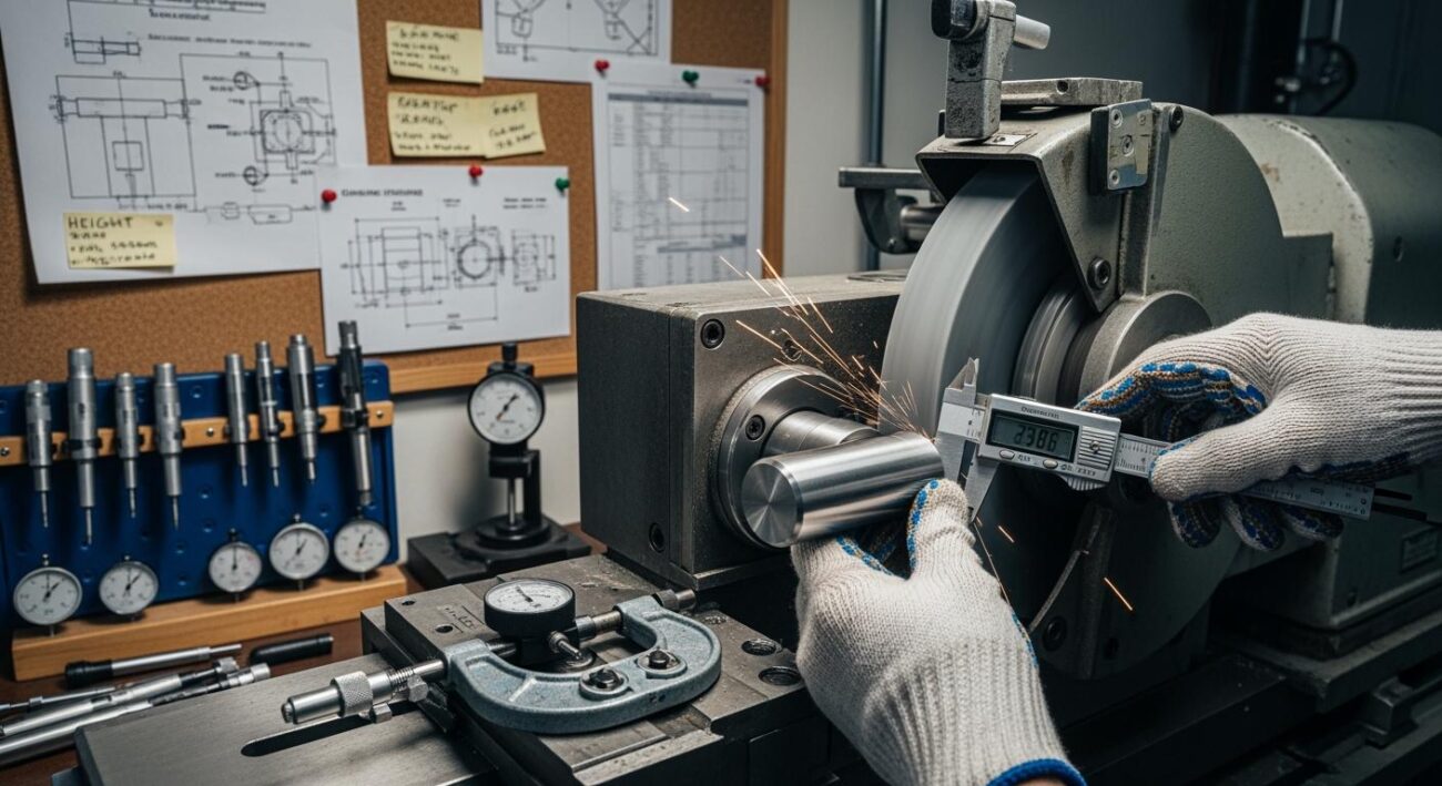
Troubleshooting Common Errors
Even with a perfect setup, errors can arise during the grinding process. These issues can cause parts to fall outside of specifications, which are often as tight as 0.0001 inches. Identifying the root cause is critical for maintaining tight tolerances. This section provides a clear problem, cause, and solution guide for the most common centerless grinding errors.
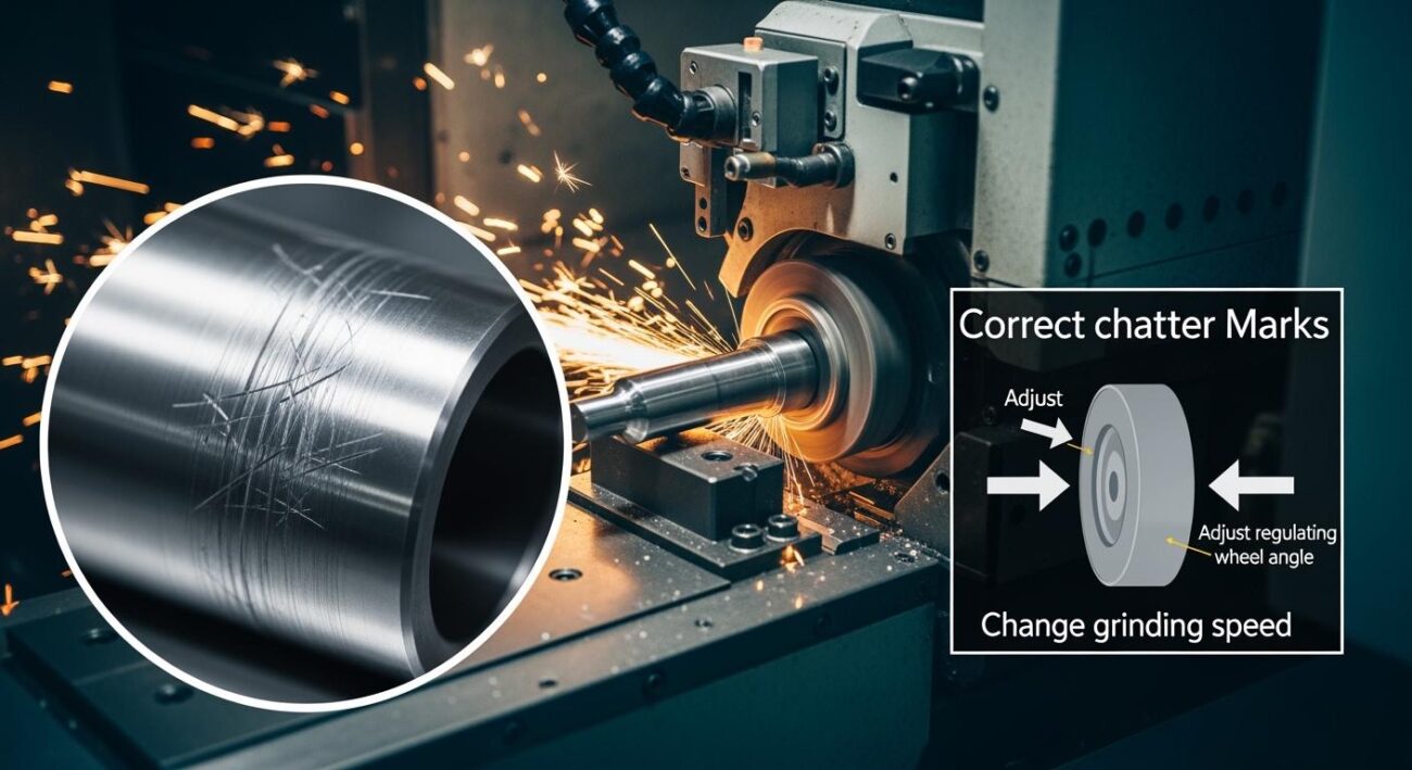
Correcting Chatter and Poor Finish
Problem: The workpiece has visible chatter marks or a poor surface finish, failing to meet quality standards.
Cause: Chatter is a high-frequency vibration. It can originate from mechanical issues or incorrect parameter settings. The appearance of multiples of the rotational frequency is often a symptom of mechanical relaxation in the system. An excessive regulating wheel tilt angle can also cause periodic workpiece chatter.
Solution:
- Reduce Speeds and Feeds: Lowering the regulating wheel speed and feed rate can decrease vibration. This change enhances the surface finish, though it may slow production.
- Adjust Wheel Speeds: Higher grinding wheel speeds can improve surface finish by increasing the number of abrasive contacts. However, excessively high speeds may cause thermal damage. For conventional grinding, wheel speeds of 30–40 m/s are effective. For precision grinding, maintaining speeds between 25–35 m/s is recommended.
- Check Component Rigidity: Ensure the workblade, guides, and workpiece are held securely. Any looseness will amplify vibration.
- Inspect Wheel Balance and Dressing: An out-of-balance grinding wheel is a primary source of vibration. Re-balance the wheel and ensure it is dressed correctly.
A Note on Microparts:
The need for high wheel speeds presents a significant challenge when grinding very small parts. Any flexing of the workpiece can cause unacceptable distortion. The goal is to prevent vibration from starting and to dampen any that occurs.
Fixing Tapered or Barrel-Shaped Parts
Problem: The workpiece is not cylindrical. It may be tapered (one end is larger than the other) or barrel-shaped (the middle is larger than the ends).
Cause: Misalignment is the most common cause of shape errors.
- Taper: This often results from the inlet and outlet guides not being parallel to the grinding wheel’s axis. A misaligned regulating wheel can also produce a constant taper, as it consistently offsets the workpiece axis. Instability in the machine, where alignment shifts under load, can also cause varying degrees of taper.
- Barrel Shape: This error typically indicates a problem with the regulating wheel’s profile. A concave shape on the regulating wheel, caused by an incorrect dresser angle, will produce a high spot in the middle of the workpiece.
Solution:
- For Taper:
- Align Guides: Re-check the alignment of your inlet and outlet guides. They must be perfectly parallel to the workpiece’s path of travel.
- Check Regulating Wheel Alignment: Ensure the regulating wheel is true and its axis is parallel to the grinding wheel’s axis.
- Verify Machine Stability: Check for worn shims or loose components that could cause alignment to shift during the grinding process. Maintaining alignment is key for tight tolerances.
- For Barrel Shape:
- Adjust Dresser Angle: A barrel-shaped workpiece means the regulating wheel dresser angle was too high. This created a concave shape on the wheel.
- Reduce the Angle: Correct the barrel shape by reducing the dresser angle. Setting the regulating wheel dresser as close to zero as possible helps avoid this error.
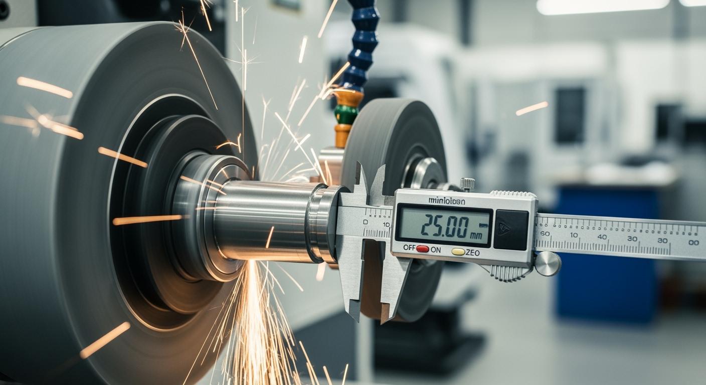
Eliminating Out-of-Roundness and Lobing
Problem: The workpiece has a consistent diameter when measured with a two-point micrometer, but it is not perfectly round. This is often an odd-numbered lobing pattern (e.g., 3 or 5 points).
Cause: Out-of-roundness is a geometric issue. It is often caused by an incorrect relationship between the workpiece, workblade, and wheels. The height of the workpiece center above the wheel centerline directly influences the rounding action. A specific tangent angle, determined by this height, can either correct or create lobing.
Solution:
- Adjust Workblade Height: To improve roundness, a common solution is to increase the height of the workpiece above the centerline. Raising the workblade changes the tangent angle and can speed up the rounding process. However, raising it too high can make the workpiece unstable. Finding the optimal height is crucial for achieving both roundness and stability.
- Modify Regulating Wheel Angle: For infeed centerless grinding, excessive axial thrust can cause lobing. Reduce the regulating wheel’s inclination angle (e.g., to 0.5° or even 0.25°) to lessen this force.
- Check Workblade Support: Ensure the workrest blade support is perfectly level and aligned. Any deviation can prevent the workpiece from rotating uniformly. This step is vital for holding tight tolerances.
Solving Inconsistent Part Diameter
Problem: The diameter of the workpiece varies from part to part, or even along a single part, making it impossible to hold tight tolerances.
Cause: Inconsistent diameter is often a sign of instability in the centerless grinding process. Two major factors are thermal expansion and coolant issues. Thermal expansion of machine components like the frame and spindle causes them to grow during operation. This growth leads to a slight shift in the tool’s position, affecting dimensional accuracy.
Solution:
- Stabilize Machine Temperature: Allow the machine to warm up and reach a stable operating temperature before starting a production run. This minimizes dimensional drift caused by thermal expansion.
- Ensure Consistent Coolant Flow:Inconsistent coolant application can lead to a built-up edge on the wheel or thermal expansion of the workpiece itself. Both issues result in size inconsistencies.
- Check that coolant nozzles are aimed correctly.
- Ensure the flow rate is constant and sufficient.
- Maintain coolant cleanliness and concentration.
- Verify Wheel Dressing: A dull or loaded grinding wheel requires more pressure, which can cause deflection and size variation. Maintain a consistent dressing schedule to ensure the wheel remains sharp and true. Proper dressing is fundamental to achieving accuracy and holding the tightest tolerances.
Achieving control in centerless grinding rests on three pillars: precise setup, optimized parameters, and diligent maintenance. A superior surface finish on each workpiece is not from one magic setting. It comes from a balanced, systematic approach. This ensures every workpiece meets specifications.
Standardize your procedures to transform results for each workpiece from inconsistent to reliable. Use setup sheets and photo documentation to ensure every workpiece is handled correctly. Partnering with a specialist like Aimgrind ensures you have the right grinding wheels for your specific workpiece, completing your strategy for a perfect workpiece.
FAQ
What is the main difference between through-feed and in-feed grinding?
Through-feed grinding continuously feeds cylindrical parts through the machine. It is ideal for high-volume production of simple rods or pins. In-feed grinding is used for parts with complex shapes, like heads or multiple diameters, grinding them one at a time.
Why is the regulating wheel so important?
The regulating wheel is critical for process control. It dictates the workpiece’s rotational speed, which directly impacts surface finish. In through-feed operations, its angle also sets the axial feed rate, controlling how fast the part moves through the machine.
How do I improve my surface finish quickly?
A quick way to improve finish is to slow down the regulating wheel speed. This action increases the number of cutting contacts on the workpiece per revolution. A slower rotation produces a smoother, more refined surface.
What wheel should I use for hard materials like ceramics?
Hard materials require superabrasive wheels for effective grinding. High-performance wheels, such as Aimgrind’s diamond grinding wheels, are designed for this purpose. They provide the necessary durability and precision to cut hard alloys, ceramics, and composites while holding their form.